
Here is an article written by our engineering team that will provide you 4 tips that will help you design sheet metal parts. Sheet metal can be shaped into a myriad of shapes due to its flexibility as explained in our previous article here: Tolerance Guidelines for Sheet Metal Design . However, certain design considerations must be kept in view when designing for sheet metal fabrication. The following tips are not meant guidelines differ from manufacturer to manufacturer. dependent on skills and machinery available.
1. Distance between extruded holes
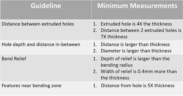
To start, we need to be considerate of the distance between features as placing them too close to each other would result in inaccuracies and increased cost to make up for the poor design.
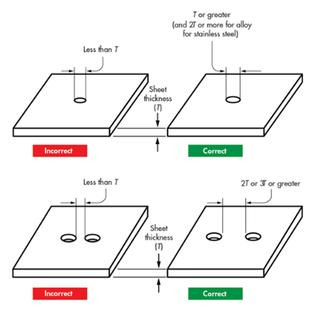
- An extruded hole should be at least 3x the thickness of the sheet.
- Between 2 extruded holes, the minimum distance is recommended to be 6x the thickness of the sheet
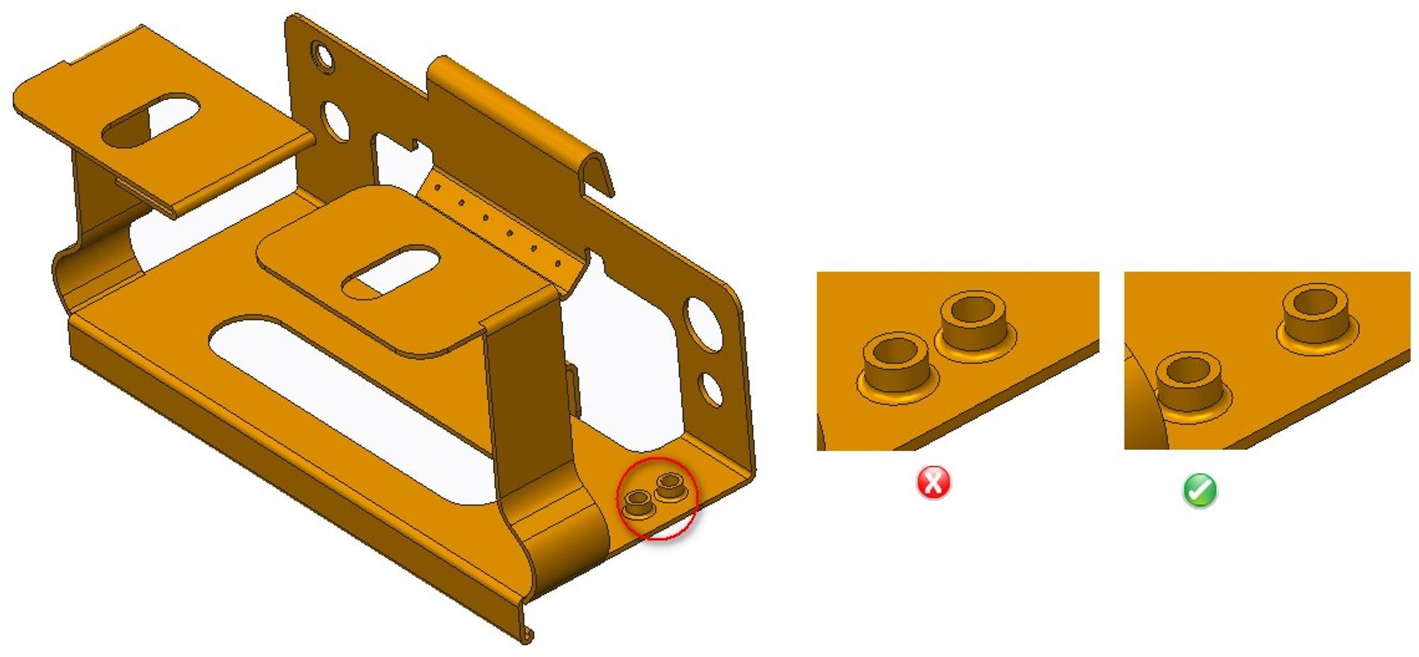
This is to prevent deformation or tearing of the edge and the hole because of the shearing process when making the holes. Further details can be found in another article that we’ve written here.
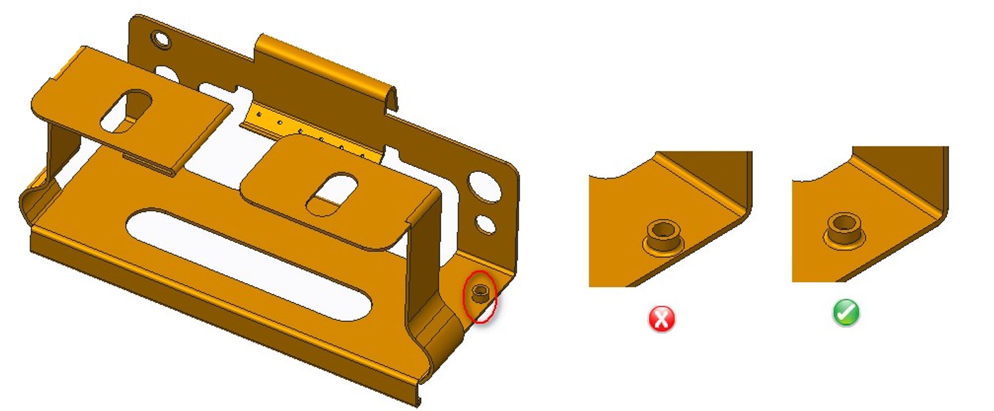
2. Hole depth and distance in between
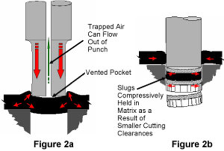
Holes should be wider than the sheet’s diameter as seen below. While this is not mandatory, following this tip would help with cost savings. This is because additional post processing steps are required to remove the excessive burrs due to the higher punching load. Additionally, the lifespan of the part would decrease due to slug pulling as the punch is withdrawn as seen below.
The distance between the 2 holes should be not smaller than the thickness of the sheet as seen below. This is to ensure the holes would not be deformed during the manufacturing process which would result in a need to have additional machining processes and thus increase cost for consumers. A more in depth article covering the cause of the issues can be found here.
3. Bend Relief for non-homogenous parts
The inner radius is generally at least 1 X the thickness of the metallic sheet. As the inner bending radius increases, the amount of strain on the edge decreases. This reduces the risk of cracking not only during the manufacturing stage but when in use as well. Cracks are formed when the stress is larger than the ultimate tensile stress, this means that ductile materials would require a smaller radius to achieve the same level of risk compared to a brittle material with a larger bending radius.
When bending non-homogenous, it is important to have sufficient distance between the edge and the formation of the bend to ensure Tearing does not occur (Part A). This should not be less than the radius of the bend.
However, when bending non-homogenous parts, Bend relief is a good way to relief the stress of the part as seen below (Part C) if your part requires the distance to be less than the radius of the bend.
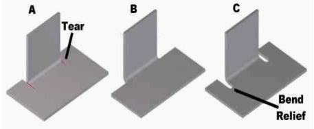
Bend relief works by cutting into the part where the tear is likely to occur (Part C). The depth of relief should be larger than the radius of the bend, however the width should be material thickness + 0.4mm. This would strengthen the part without having too large an impact on the dimensions of the part.
4. Features near bending zones
As sheet metal changes shape through bending, it is important to check that there are no critical holes that intersects the bending radius as this would deform the hole. Having a feature too close to the bending may result in the feature being stretched in the process.
Thus, as a rule of thumb, the distance between the hole and the bending radius should be 4x the material thickness. This distance should generally be sufficient to prevent warping of features, however this varies for different manufacturers.
Using the same fillet radii for multiple or all bends would enable consumers to enjoy added cost savings! Likewise, designing bends on the same side would save time for the manufacturers and thus cost savings for consumers.
5. Conclusion
When designing for sheet metal fabrication, one needs to consider the process of manufacturing to ensure the design is manufacturable and not just functional or aesthetically pleasing as mentioned in our earlier whitepaper on Tolerance Guidelines for Sheet Metal Design.
Here is a short recap of what was covered in this whitepaper.
Some design guidelines have been covered in this whitepaper, however there are other considerations one needs to consider when designing for sheet metal fabrication as each design has its own restrictions and issues.
Conclusion
When designing for sheet metal fabrication, it's essential to consider the manufacturing process. A design that is only functional or aesthetically pleasing may not be manufacturable, or it could be excessively expensive to produce. By understanding and applying key design guidelines such as maintaining proper distances between holes, using bend relief, and avoiding critical features in bend zones, you can create parts that are not only high-quality but also cost-effective to produce. These best practices help minimize material deformation, reduce the need for costly post-processing, and ensure your final product meets your exact specifications.
At Factorem, we bridge the gap between design and manufacturing. Our team of experts understands the nuances of sheet metal fabrication and can help you optimize your designs for production. By leveraging our network of skilled manufacturers, we ensure your parts are made accurately, on time, and within budget. Get an instant quote today and let us help you bring your sheet metal designs to life.


