
What is a Fit?
When designing a part or assembly, engineering fits are typically employed as part of the geometric dimensioning and tolerancing process. In engineering jargon, the “fit” is the clearance (or overlap) between two mating components. The magnitude of this clearance determines whether the parts may move or rotate independently of each other or are temporarily/ permanently linked at the other. As a result, a fit is utilised to explain the components’ dimensional connections. It determines if the components are slack or tight, which assists in the sliding or pressing characteristic. Engineering fits are sometimes referred to as “shaft and hole” pairings, however they are not confined to only round components.
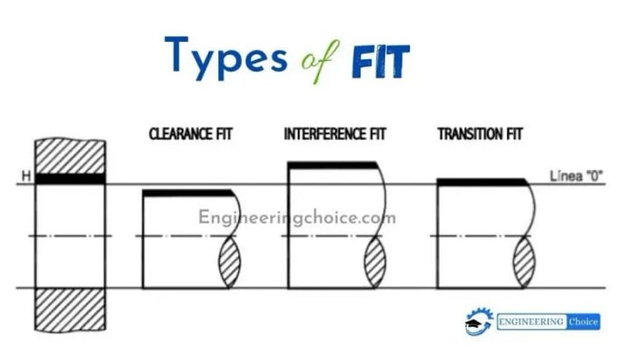
Type of Fit
- Clearance: The hole is larger than the shaft, enabling the two parts to slide and / or rotate when assembled.
- Transition: The hole is fractionally smaller than the shaft and mild force is required to assemble/disassemble.
- Interference: The hole is smaller than the shaft and high force (eg. hammering/hydraulic press) or heat is required to assemble/disassemble the parts
Clearance Fit
A clearance fit is utilised when loose mating and unrestricted movement of components are required. As a result, they are suitable for creating items whose components must easily move in and out.
Clearance fittings feature a shaft that is smaller than the hole. This has two consequences. The first is a maximum clearance, in which the shaft has the smallest diameter and the hole has the largest diameter. The other is the minimal clearance, in which the shaft is at its maximum and the hole is at its smallest.
Clearance fits are further divided into five categories classified based on how loose they are. Below are the different types of fits under this category:
- Loose running: Larger clearance where accuracy is not essential
- Free running: Large clearance where accuracy is not essential and involves high running speeds, large temperature variations, or heavy journal pressures
- Close running: Small clearances with moderate requirements for accuracy,
- Sliding: Minimal clearances for high accuracy requirements, which can be easily assembled and will turn & slide freely
- Location: Very close clearances for precise accuracy requirements, which can be assembled without force and will turn & slide when lubricated
Interference Fit
A press fit or friction fit is a method of connecting two components together by forcing them together. The fastening occurs through a variety of methods and requires a significant amount of force to couple and uncouple the components. The process also determines which kind of interference fits to utilise.
The Maximum Interference in an interference fit is the difference between the maximum size of the shaft and the minimum size of the hole. The Minimum Interference is also the difference between the minimum size of the shaft and the maximum size of the hole.
There are two sub categories for Transitional Fit which is stated below:
- Pressed fit: Negligible clearance or interference fit which can be assembled or disassembled as assembling is via cold pressing
- Driving fit: These fits have a more prominent interference fit than press-fit, and it needs higher assembly force for cold pressing.
- Transition Fit: These fits are intermediate between clearance and interference fits and are suited for circumstances where precision is critical. A possible use case could be to align mating components where exceptional accuracy is needed.
- Transition fittings are also known as slip or push-fit by engineers and machinists. When the degree of clearance is compared, they have a greater clearance than an interference fit. However, the clearance is insufficient to ensure joint mobility. Depending on the scenario, transition fits might give clearance or interference fit.
- Transition fit can be split into two sub categories:
- Similar fit: Negligible clearance or interference fit which can be assembled or disassembled with a rubber mallet
- Fixed fit: Negligible clearance or small interference fit which can be assembled or disassembled with light pressing force
Tolerance Chart (ISO 286)
Generally, engineers use a fit/tolerance chart which contains the recommended hole and shaft diameters for a range of different fits. During the development process, an engineer may choose one or more, depending on the exact use case. More than one is generally made, tested and then fabricated.
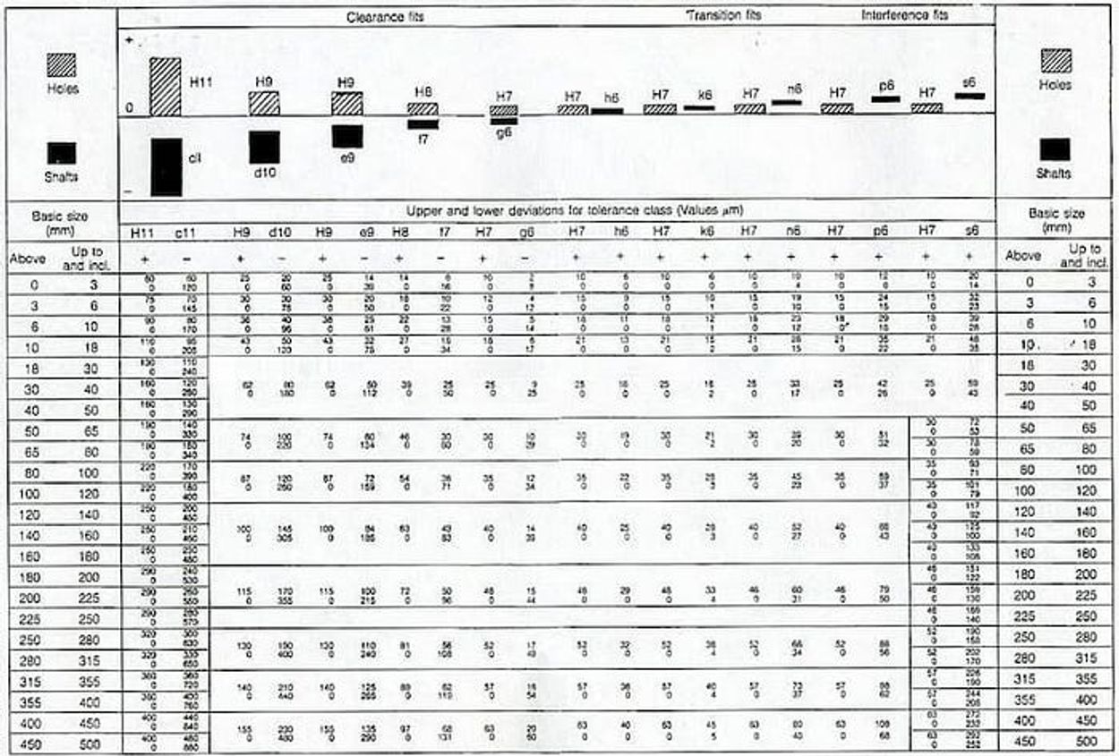
The fit combination (i.e. hole and shaft is determined using an alpha-numeric code). In the hole base method:
- A hole tolerance is indicated by the capital letter, e.g. H7
- A shaft tolerance, is indicated by a lowercase letter, e.g. e5
Link for a detailed table may be found here
Conclusion
Understanding the various types of engineering fits—clearance, transition, and interference is fundamental to designing functional and reliable mechanical assemblies. The correct fit ensures that components either move freely, align precisely, or are permanently joined, preventing issues like premature wear, assembly difficulties, or part failure. By referencing standardized tolerance charts like ISO 286, engineers can select the ideal fit for their specific application, balancing performance needs with manufacturing feasibility. This knowledge is crucial for creating robust designs that function exactly as intended.
Factorem's expertise in manufacturing is built on these foundational principles. We work with our network of experienced partners who understand the importance of precise fits and tolerances. When you provide your design specifications, our team ensures they are accurately translated to the manufacturing process, guaranteeing that your parts are fabricated to your exact requirements. Get an instant quote today and partner with us to bring your precision-engineered designs to life.


