This article will guide you on the ISO 2768 based tolerances that Factorem bases its machining standards on. Tolerancing can greatly influence the way in which parts fit together into an assembly and is thus extremely important. If you submit a part, with incompletely listed tolerances, these are the standards that we follow.
1. Introduction
Tolerance refers to the permissible degree of variation for a particular feature or geometry of a part. Tolerances are carefully taken into account when a part or assembly is designed, to better suit practical machining and assembly limitations that may lead to deviations, affecting the end use-cases.
As we know, machining is a process that can be carried out in differing levels of accuracy and precision. The closer or tighter that we control features, the more expensive it gets, this is because the operator or machine has to spend longer performing the task. Moreover, for general use cases, controlling features very tightly has no merit, since end use-cases can be satisfied with parts of relatively lower precision and/or accuracy. If a part is dimensioned correctly, the designer’s intent, thought process and assembly requirements are all clear to the machinist.
This paper highlights Factorem’s internal machining tolerance guidelines, to be followed in the following use cases:
- The customer doesn’t provide a technical drawing of the uploaded part for a subtractive machining process.
- The customer doesn’t provide tolerance guidelines on the uploaded technical drawings.
- The customer asks for a recommendation on the tolerance guidelines for his/her part.
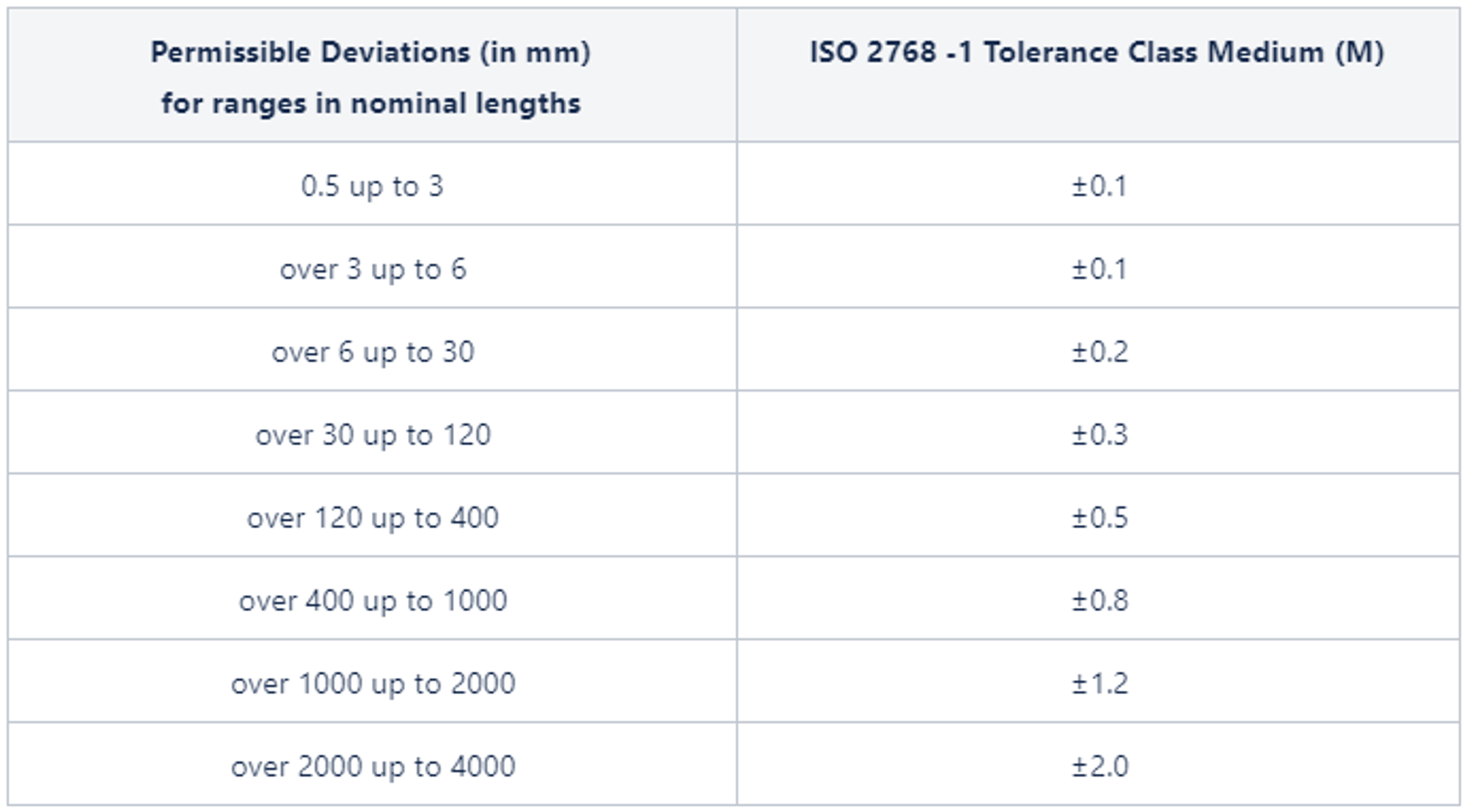
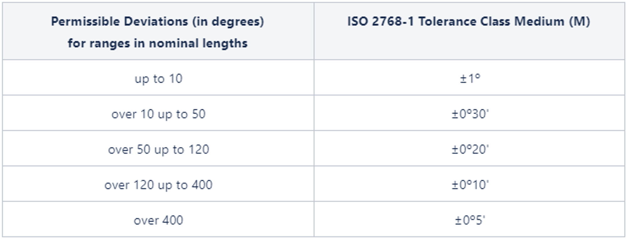
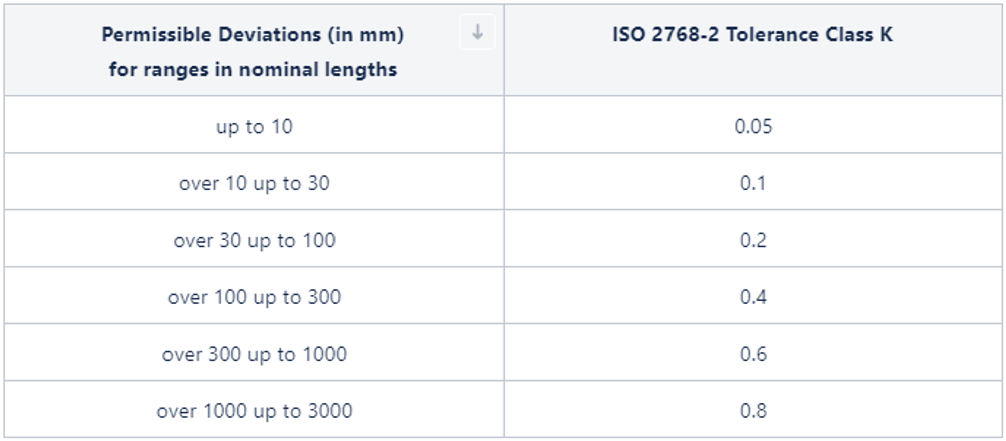
General tolerances for linear and angular measures fall into one or more tolerance classes (as stated in ISO2768-T1 and ISO2768-T2), indicated in the following sections. The default tolerance guidelines for each of these have been indicated in the relevant sections as well.
This document states the relevant tolerance standards at Factorem. Factorem has followed relevant ISO standards (ISO2768-T1 and ISO2768-T2) to derive these guidelines.
If the customer requires tolerance classes deviating from Factorem’s standards, then he/she must indicate this on the technical drawings, to be provided with the relevant 3D files.
2. General Tolerances for Linear and Angular Dimensions (ISO 2768 T1)
2.1 Linear Dimensions

2.2 External Radii and Chamfers

2.3 Angular Dimensions

2.4 Flatness

2.5 Perpendicularity

2.6 Symmetry

2.7 Run Out(s)

Conclusion
ISO 2768 tolerances provide a crucial framework for ensuring parts are manufactured correctly, even when technical drawings lack detailed specifications. By adhering to these standards, we ensure that parts with incompletely listed tolerances still meet a clear, defined level of precision. This approach not only prevents ambiguity and miscommunication between designers and manufacturers but also helps manage costs by avoiding unnecessary and expensive over-tolerancing for non-critical features.
At Factorem, we use ISO 2768 as our baseline for all machining orders to guarantee consistent quality and a smooth production process. This commitment to standardized tolerances allows us to deliver high-quality parts that meet a designer's intent, on time and on budget. Get an instant quote today and experience the reliability of our professional machining services.


